 boo@zjmgmm.com / 958587858@qq.com
 English
 русский
 Español
 عربى
عربىLithium battery technology continues to evolve to meet the demands of modern applications, innovative designs like the flex stacked battery. This configuration aims to balance performance with adaptability, though it presents a unique set of advantages and challenges.
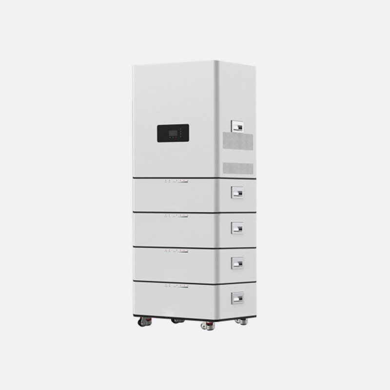
Modular Flex Stack Design
Features:
The core feature of this design is its modularity. Individual pouch or prismatic cells are connected using flexible conductive interconnects, such as braided copper straps or flexible printed circuit boards (PCBs). This creates a "stack" of cells that can be bent or shaped to a limited degree. This flexibility allows engineers to fit the battery into irregularly shaped spaces within a product, optimizing the use of available volume. The modular nature also simplifies maintenance and repair, as a single faulty module can often be replaced without discarding the entire battery pack.
Disadvantages:
The primary disadvantage of this modular approach is the increased mechanical complexity. The numerous interconnection points between modules are potential points of failure if not secured properly. Vibration and repeated flexing can fatigue these connections, increased electrical resistance, localized heating, and potential failure. Furthermore, the system requires a more complex Battery Management System (BMS) to effectively monitor the voltage and temperature of each individual module, adding to the overall cost and design challenge.
Integrated Flex Stack Design
Features:
This design takes the concept further by embedding individual electrode layers and separators into a single, continuous, flexible package. Rather than connecting discrete cells, the entire stack is manufactured as a unified, bendable unit. This integration can a higher energy density within the flexible form factor because it reduces the amount of inert packaging material needed for individual cells. It offers a more robust and seamless flexibility compared to the connected-module approach.
Disadvantages:
The integrated design suffers from significant manufacturing complexity, which currently results in a higher production cost. Repair is virtually impossible; if one section of the integrated stack fails, the entire unit must be replaced. This design also faces greater challenges in thermal management. Dissipating heat effectively from within a dense, folded, or bent stack is difficult, which can limit its performance in high-power applications and potentially impact the long-term health of the cells due to elevated operating temperatures.
What Are the Different Types of Power Terminal Blocks?
Power terminal blocks are fundamental components in electrical systems, providing secure and organized points for connecting and distributing electrical power. They are designed to handle high currents and are critical for safety and reliability. Different types are suited to specific applications based on their design and features.
Barrier Terminal Blocks
Features:
Barrier terminal blocks, also known as European-style or DIN rail-mounted blocks, are among the common types. They feature a sturdy insulating body, typically made from polyamide or other robust plastics, that is mounted on a standard DIN rail. Each connection point has a metal clamp (usually brass or copper alloy) secured by a screw. The design includes physical barriers between each terminal to prevent accidental short circuits between adjacent wires. They are known for their strong, reliable screw-down connection, which is effective for solid and stranded wires when used with a ferrule.
Disadvantages:
The main drawback is the relatively slower installation and maintenance time, as each screw must be torqued individually. Vibration can potentially loosen screw connections over time if not properly secured, necessitating periodic re-tightening. They also require more space on a panel compared to some more compact alternatives.
Spring-Clamp Terminal Blocks
Features:
Spring-clamp terminal blocks use a constant-force spring mechanism to clamp the wire, rather than a screw. A tool is inserted into a release lever to open the clamp, allowing the wire to be inserted. When the tool is removed, the spring closes and maintains consistent pressure on the conductor. This design allows for much faster, tool-efficient wiring, which is a significant advantage in large-scale manufacturing. The spring mechanism maintains tension, providing resistance to vibration-induced loosening.
Disadvantages:
The initial cost per terminal is often higher than that of simple barrier blocks. They can have limitations on the types of wire they accept; for instance, very fine-stranded wire might not be held as securely without a specific ferrule. Troubleshooting and modifying connections can be slightly more difficult than with a simple screw terminal, as they require the specific tool to release the clamp.


 English
  Building 33, Demonstration Park, No. 318 Chenguang Road, Eastern New District, Wenling City, Taizhou City, Zhejiang Province, China
  0086-576-86337978
  0086-576-86333878
 boo@zjmgmm.com